PCB simulation
The PCB simulation, without the hand-waving.
When a tool says it simulates your PCB, suspicion is the right reflex. This page says what Nihil computes, at which fidelity, how every answer is checked and where the model stops, with numbers from the demo's own runs. Nothing here describes something that is not built.
1 nsthe first step after every edge; the error estimate grows it to 50 µs at most
675copper elements in the RC car's solve at Full PCB, 500 of them on car_ctrl
195references behind the demo's models, each opened and verified, with the date
0.009xreal time, both RC car boards on copper and driving. Slow, and it says so
Four things run together
A board simulation in Nihil is one transient run of the circuit, with the board's own firmware on its chip and, once the board is routed, its real copper in the matrix. Around it, a digital twin plays the world the board lives in. Several boards of one product share one matrix, joined by their cables.
| Piece | What is computed | How |
|---|---|---|
| The circuit | Every modelled part, from a resistor to a battery pack: 36 model kinds in the engine, and a project can add its own | Modified nodal analysis, solved in the time domain |
| The copper | Every routed track, via and pour, read from the KiCad board after routing | A resistor per piece at its own temperature, dissipating where it runs |
| The firmware | Your C application, unchanged, on the chip model's pins | Compiled for your PC, run on a fiber; a blocking call waits in simulated time |
| The heat | A thermal grid per board, 1 mm cells by default, coupled both ways to every part and track | Its own backward-Euler step, 1 ms by default |
| The cables | Each harness conductor: resistance, inductance, contact resistance, its own temperature | In the same matrix as the boards they join |
| The world | What the board drives and senses: on the RC car, the body, tyres, gear and walls | The twin, a fixed 1 ms tick, exchanged with the circuit at every tick |
How much of each board is solved
All of that is slow, so you choose per board. The app names the levels Copper, Circuit and Chips; files say full, light and io. A fourth, port, replaces a finished board with the connector currents of one full run, replayed.
| Level | What is solved | On the demo |
|---|---|---|
| Copper | The circuit as declared, switching edge by edge where a scenario asks, with the routed copper | Both RC car boards: 0.008x to 0.019x real time |
| Circuit | Converters and PWM averaged, no copper, a thermal grid four times coarser | One car board at Copper, one at Circuit: 0.12x |
| Chips | The chips, sensors, inputs and outputs against ideal rails; nothing else | The car's 14.2-hour run to a flat pack in about 35 s |
A lower level is not free. On the PWM drive's 1 kHz switching run, the generator board at Circuit came out 44 % off at its worst point, though the verdict held, so the docs tell you to use port there instead. And a check that needs more than its level ran fails with fidelity_ok = false and the reason: ripple needs real edges, an I2C rise time needs the electrical bus. It is never skipped and never passes quietly.
How much of the copper is solved
A second dial, per run, from copper = 0 to 3:
| Level | What the copper is |
|---|---|
| 0 | Ideal wires: the circuit exactly as if the board were not routed, to the same trace hash |
| 1 | The default once a board is routed. Tracks and vias as resistors R(T); each pour solved once as a mesh and fitted to a star between its pads |
| 2 | Every pour kept as its full resistor mesh on the thermal grid's cells; the long thermal scenarios ask for it |
| 3 | Parasitic, for ESD strikes: the inductance of every track piece, via and package lead, and capacitance to the planes |
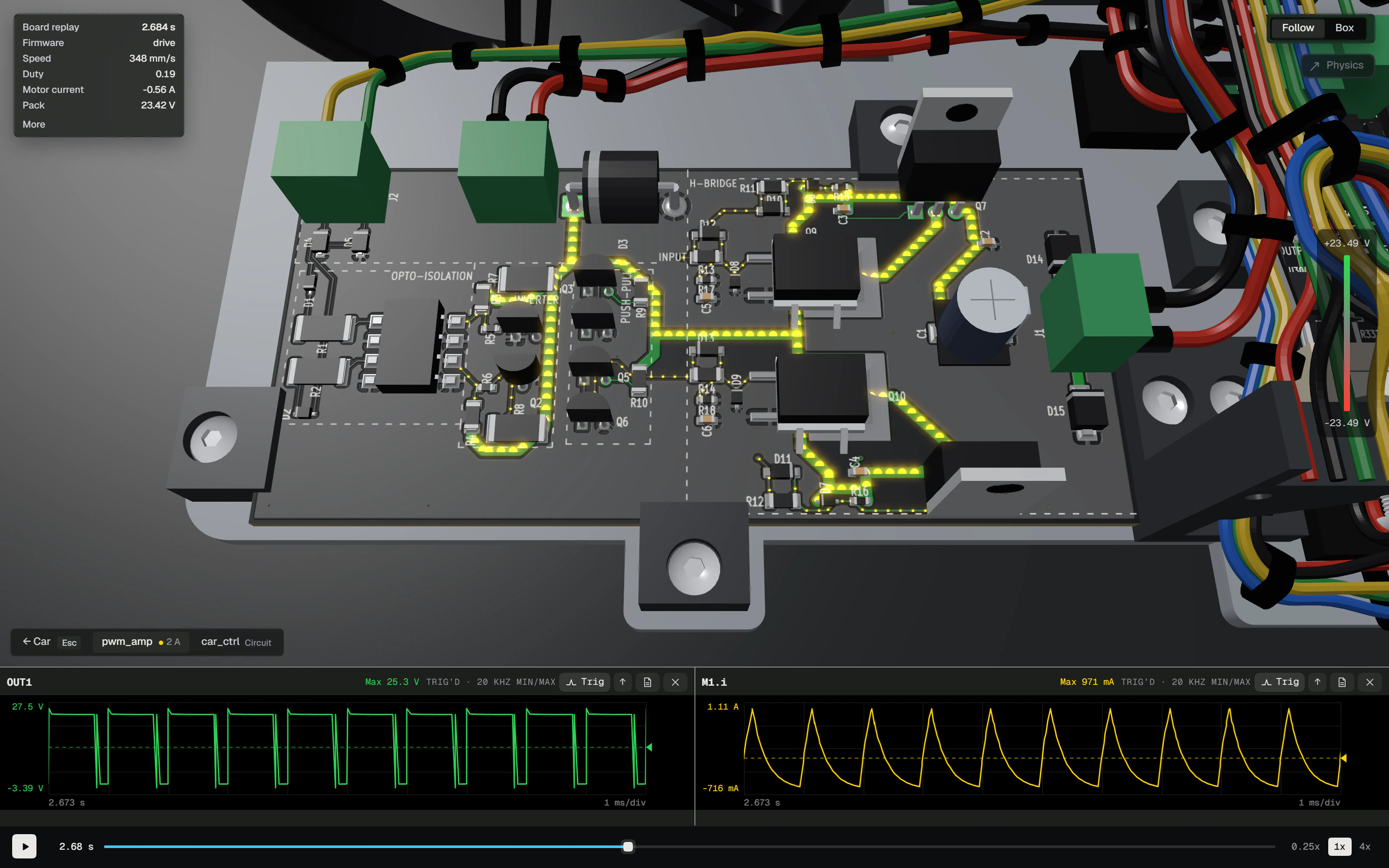
What a solve is
The circuit engine is a transient simulator written for one job: judging a board before it is ordered, with its firmware running on its pins. C++17, the solve on one thread, no wall clock anywhere in the model. A run starts from a DC operating point (Newton, then gmin stepping, then source stepping, after ngspice) or from a saved snapshot, and then, step after step:
- Pick the step. 1 ns after every breakpoint, then as long as the local truncation error allows, up to 50 µs, never past the next edge. A breakpoint is anything that must land exactly: a PWM edge, a bus edge, the end of an ADC acquisition, a regulator entering current limit.
- Pick the method. Backward Euler for two steps after a breakpoint, trapezoidal after that, and a second-order Gear retake for any step whose trapezoidal attempt rang.
- Solve. Newton-Raphson on the nonlinear parts, with SPICE3's junction and FET limiting, over a sparse LU: a minimum-degree ordering fixed once, threshold pivoting, a re-pivot when the pivots grow 1e8-fold. Converged means within 0.1 % relative, 1 µV and 1 pA. Fifty iterations without that rejects the step and halves it.
- Accept. The truncation error is judged on charges and fluxes, so a nonlinear capacitor conserves its charge. Then the thermal grid steps when its 1 ms boundary passes, and the firmware ticks when its boundary passes.
A step that would shrink below the floor stops the run and names the element responsible. It never shrinks into silence.
What each element is
- A track piece: R = ρ(T) L / (w t), copper's 1.68e-8 Ω·m at 20 °C rising 0.393 % per kelvin, t from the copper weight. T is the track's own grid cells plus the constriction into the laminate, so a warm track has a higher resistance.
- A via: its barrel's plating, layer to layer.
- A part: datasheet-level. SPICE3 junction and level-1 MOSFET equations where those exist; behavioural models for regulators, bridges and the battery's open-circuit curve with its RC pairs. The constants come with their source: a datasheet table, a paper, or a bench row when no document prints them.
- A chip: output pins are Thevenin drivers from the datasheet's VOH and VOL at their test currents, inputs are leakage, clamp diodes and Schmitt thresholds, and an ADC input is a sample-and-hold that closes for its acquisition window.
Your firmware, on the chip
The application is compiled for your PC and runs on a fiber against the chip model's hardware table. A GPIO write moves a driver. An I2C read clocks real edges against the pull-ups inside an electrical window, or hands bytes to the device model outside one. A blocking call parks the fiber with "wake me at t" while the circuit keeps stepping; nothing inside a call steps the circuit. The ESP32-P4 and the STM32G030F6 run through hand-made tables; seventeen more microcontrollers (AVR, ESP32, RP2040 and RP2350, STM32F4, SAMD and the Teensy 4's i.MX RT1062) run at register level, from kits generated out of their vendors' register files. The NVIDIA Jetson Orin Nano is a Linux computer: its program runs as it is, with real CUDA, and its devices are simulated at the operating system's boundary; the Orin NX, the AGX Orin and the Raspberry Pi 5, 4 and Zero 2 W have board profiles on the same path.
A tick still parked in a transfer when the next one is due counts as an overrun, and scenarios judge the count. The RC car's firmware overruns two at start-up: it writes each sensor's 91-byte configuration in one I2C transfer, 2.1 ms at 400 kHz against a 1 ms tick. Its scenario allows exactly those two and says why.
The numbers, from one run
The demo's PWM drive: a generator board with an STM32G030 running its firmware, an opto-isolated amplifier board, a 6S pack and a gearmotor. 105 parts, 50 nets, two routed boards. The scenario spin_up drives the motor from rest for 0.8 simulated seconds, once with ideal copper and once with the routed copper at its default level:
| Copper 0 | Copper 1 | |
|---|---|---|
| Copper nodes | 0 | 391 |
| Copper elements | 0 | 392 |
| Accepted steps | 273,517 | 364,251 |
| Motor current at stall | 2.756 A | 2.747 A |
| Lowest pack voltage | 23.024 V | 23.025 V |
| Wall time | 10.1 s | 28.0 s |
| Verdict | pass | pass |
KiCad holds 630 track segments and 36 vias on those two boards. Every routed net except ground became 391 nodes joined by 392 elements: 376 track pieces and 16 vias, each heating the board where it runs. The copper took 9 mA off the stall peak and made the run 2.8 times slower. Ground, with its 189 segments, 20 vias and four pours, stayed one ideal node. That is the default, and the run's own result says so in a fidelity note. A board that declares split ground gets its return currents solved too.
For scale, the RC car's gate, two boards, 150 parts and 73 nets: sensors_up resolves every I2C edge between 0.2 and 0.4 s and takes 514,661 steps for half a simulated second (SCL rises in 123.5 ns against the 300 ns limit, zero bit errors); short_drive takes 214,398 steps for 1.6 s. The whole 14-step run, both circuit gates included, took 315.5 s.
The world around the board
The twin steps at a fixed 1 ms tick. On the RC car the mechanics take four 0.25 ms substeps per tick: tyre slip with a relaxation length, rolling resistance, load transfer, the gear and the walls. At Copper or Circuit the motor and the pack are the circuit's: the wheel's speed goes to the circuit's motor and its torque comes back, the walls' distances drive the time-of-flight sensor models, and the box's air sets the boards' ambient. Every exchange happens once per tick, held constant across it.
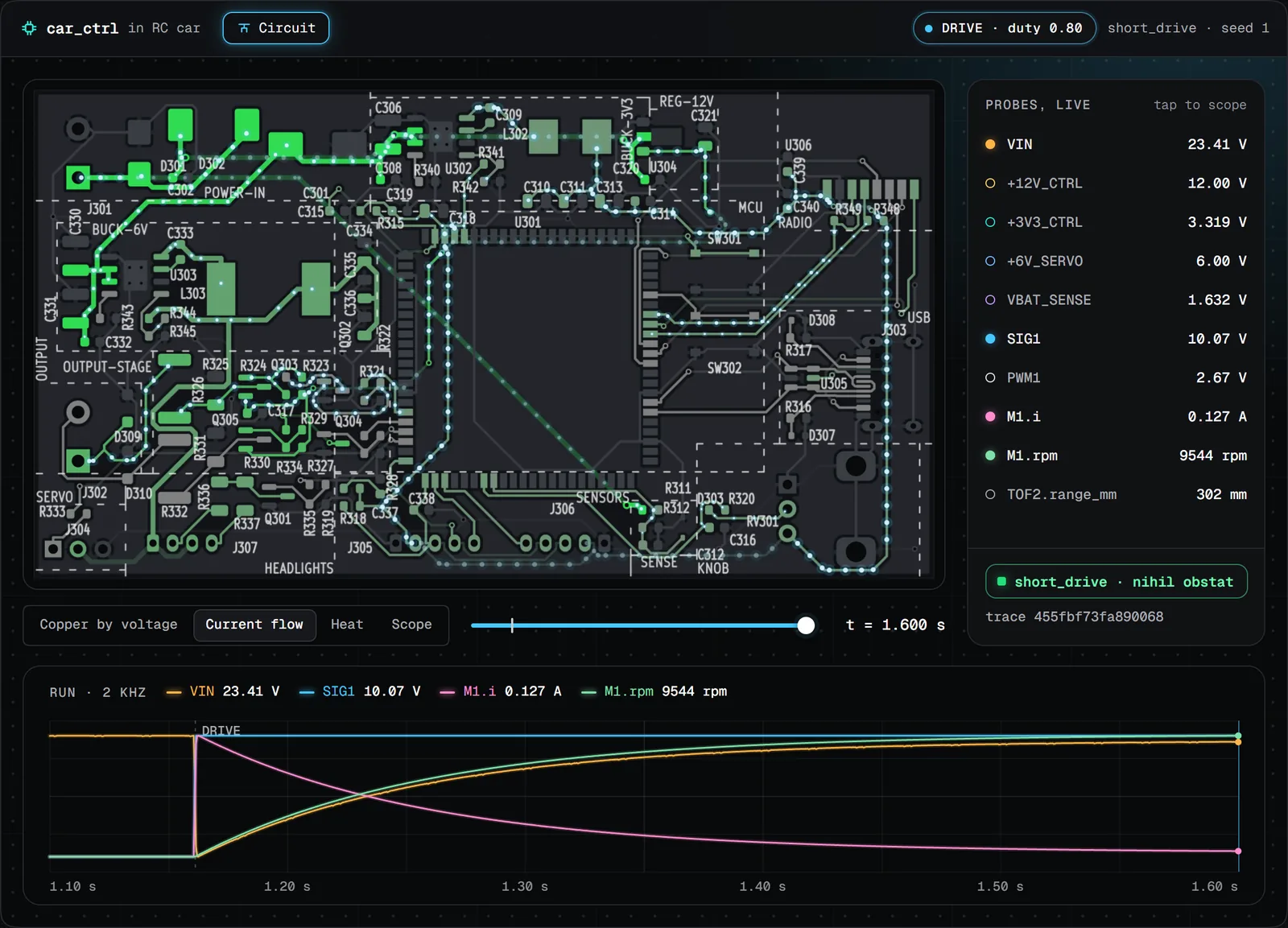
How you know it is not making things up
Same inputs, same bits
The build forbids fused multiply-adds and fast math, the models' exponentials and logarithms go through the engine's own deterministic versions, and nothing in a run reads the clock. The same netlist, scenario and seed give the same trace hash, an FNV-1a over every byte of the trace. Measured: the clang and MSVC builds give identical hashes on all ten rows of the suite, and the browser's WebAssembly engine matches the native one to 1e-9 relative on all 9,057 values of a frame, after 10 ms of the demo's rangefinder board. The run above, run again: the same hash.
The gate
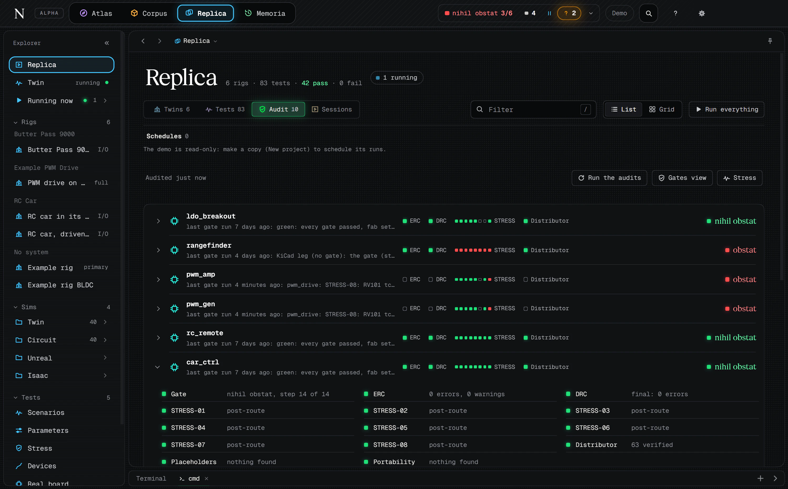
Steps 2 and 12 of the board pipeline run every scenario in the board's matrix through this engine, once before KiCad is opened and again on the routed copper. Eight stress rules judge what the runs did:
| Rule | Judges |
|---|---|
| STRESS-01 | Every pin inside its absolute-maximum window at every step; an unrated supply or input pin is itself a finding |
| STRESS-02 | Every part's dissipation against its rating |
| STRESS-03 | Capacitor voltage derating, in the time domain |
| STRESS-04 | Every rail inside its window after settling, start-up overshoot included |
| STRESS-05 | PTC, eFuse, connector, pack and source currents against their continuous ratings |
| STRESS-06 | Bus rise times, logic margins, set-up and hold, zero bit errors |
| STRESS-07 | A Monte-Carlo sweep over the declared tolerances |
| STRESS-08 | Junction, case, winding, cable and copper temperatures against rating minus margin |
A rule the board's own declarations call for, and that no run evaluated, fails a full run. A step that did not run keeps the run red. Skipping is not passing.
It says no to its own demo. The PWM drive's gate of 8 November 2026 came back obstat: in a 300-second soak at the hottest ambient, the duty potentiometer's case reached 60.98 °C against a 60 °C limit (its 70 °C rating minus a 10 °C margin), and a battery-drain run turned the motor at 742 rpm against the 3,000 it asked for. A row can also be required to fail. clock_20k asks the opto-isolated amplifier for 20 kHz, faster than its coupler's edges allow; the gate counts the row as met only because it failed.
Tolerances
STRESS-07 draws every declared tolerance across many built units. The RC car's supply question ran 10,000 units with none violating, at 137 units a second on the CPU, on a 19-node sub-circuit cut from the full board. Every cut is listed with the assumption it makes: the load it replaced draws the same current whatever the swept parts do. The PWM drive's 10,000-unit sweep gave the same bits on the CPU and on a CUDA GPU.
Every number has a source, or a bench row
A model constant cites a row of the project's citation register: the paper or the datasheet table, and the date someone opened it and checked it. The demo's register holds 195 references, every one marked verified with a date and how; the engine's code carries 100 distinct citation tags. A tag without a verified row fails the audit gate.
A constant no document prints gets a BENCH row instead: the design value, the test that would settle it, and the range the design tolerates. B-RF-10, for example, is the ESP32-P4 ADC's sampling capacitance, 4 pF by design because neither the datasheet nor the reference manual states it, with the scope set-up that would measure it. The demo has 135 such rows. None has been measured yet.
When one is, the rule is fixed in advance. Inside the tolerated range, the measured number replaces the design value everywhere it is cited. Outside it, the design is reopened. The range is never widened to fit. The twin gets the same treatment: a capture from the real device replays against it and the answers are compared byte for byte, by message kind or by counts, and a replay with nothing to compare fails.
What it does not do
- It is not SPICE. It reads its own netlist, not SPICE decks, and there are no transistor-level models of an IC.
- No harmonic balance. The engine runs transient, DC and AC small-signal analysis (sweeps, loop gain, noise at a rest point, poles). It has no harmonic-balance analysis, no zeros of a transfer function and no noise analysis of a switching stage, and an AC run needs a rest point: a switching stage or a moving source is refused.
- No signal integrity in the gate. At copper 1 and 2 a track is a resistor: no inductance, no capacitance, so no reflections and no crosstalk. Ground is one ideal node unless the board asks for split ground. Copper 3 adds inductance and capacitance for ESD strikes, quasi-statically: no retardation, and parallel tracks over a plane get no mutual inductance.
- Fields go one way. The radiated-emissions solver, a full-wave FDTD, radiates the circuit's recorded currents; the field never acts back on the circuit, so radiated immunity and field-coupled crosstalk are not modelled. Its limits ship for FCC 15.109 only, read with a peak detector as an upper bound of quasi-peak. Neither field solver is in the demo boards' gates today, and a run takes minutes on a large GPU or hours on a CPU.
- No RF. A radio link is packets through a shared simulated air with a loss setting: no RF channel, no antenna, no link budget.
- Not cycle-accurate firmware. Your C runs host-compiled, at tick granularity. An interrupt waits for the next tick or call where the silicon would preempt; caches, bus arbitration, startup code, vector tables, the linker and an RTOS belong to the target build and the bench.
- Heat in two dimensions, in still air. One temperature per column of board, 1 mm square by default, with convection as a fixed coefficient and no airflow. A cable between two boards carries no heat from one to the other.
- Batteries without a past. No ageing, no hysteresis, no cell imbalance; the curve is the datasheet's at 25 °C.
- Not real time. Both RC car boards on copper run at about a hundredth of real time. That is why the levels exist.
- Not a bench. A pass means the models, with their cited sources and their design values, say the board holds. It stays a model result until the bench agrees.
Check it yourself
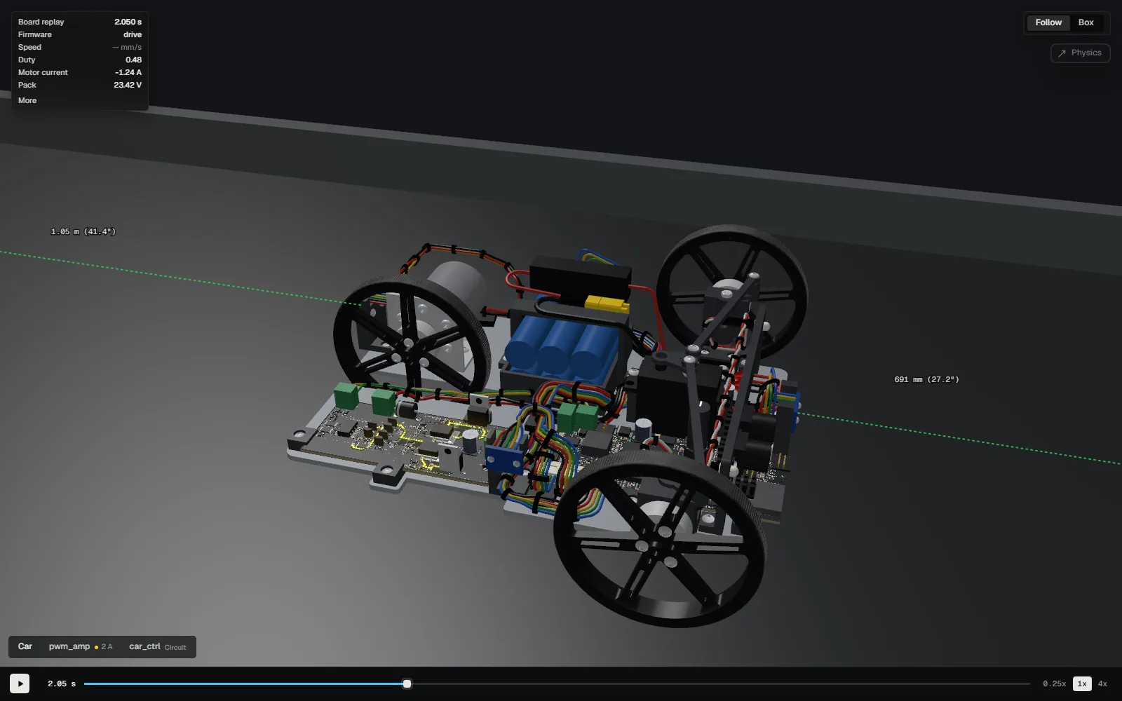
The Product page plays a recorded Full PCB run of the RC car in the real Sandbox: fly into a board, put a scope on a net, scrub the run. It is a recording, not a solver, and it says so. The demo opens the whole project in the real app, in a tab. It carries no engine: its circuits play recorded runs of this one.
The run above is one line on the engine's own runner (in the app, nihil sim run hands it the same arguments), and it prints what it judged:
hil_circuit_run pwm_drive_netlist.json spin_up.cscn --seed 1
[circuit] spin_up seed 1: PASS max_abs(M1.i)=2.74684 mean(M1.rpm)=9643.09 ... min(VIN)=23.0248
[circuit] spin_up seed 1 trace fnv1a64=c4d1c3ed6b82de98 steps=364251
Same inputs, same seed, same build: the same hash. That is measured across two compilers on x86-64 Windows; another CPU architecture gets measured before anyone claims it. If yours differs on the same build, that is a bug, and we want to hear about it.
See it run on a real board.
The demo project is an RC car, its two boards, its twin and every gate’s record, in the real app, read-only, in a tab. The desktop app is in invite-only alpha for Windows, macOS and Linux.